Tuesday, April 24, 2012

Revit Getting Started Guide: Creating a Solar Study

"create an animation of the solar activity at a particular place and time in order to study
the light and shadows that affect the building site."


1 Open a 3D view.

2 Adjust Shadow intensity, under View tab and Graphics panel, click the small arrow to the right of the word "Graphics" to open the "Graphic Display Options" dialog box. (keyboard shortcut = GD)
■ Under Shadow, verify that Cast Shadows is selected, and for Contrast, specify 24.

3 Modify the Sun Settings, Click the Sun Icon then, Sun Settings... to open the dialog box.
(the icon is in the Visibility settings menu at the bottom of the view screen)

4 select a city near your location, and click OK.
■ For Date, enter 6/22/2012.
■ For Time Interval, select 15 minutes.
■ Clear Ground Plane at Level so that the shadows fall on the terrain.
■ Click Apply, and then click OK.

5 Preview the solar study, click the sun icon to access this option.

6 Export the animation:
Click File menu ➤ Export➤Images and Animation➤Solar Study

Click ok to save the .avi file to the desired location.


Revit Rendering

I am experimenting with rendering, I will post links to helpful hints and some of my own findings as they come.
First few passes:


JPEG, High quality setting

First note, saving to TIFF loses the "sky" and JPEG retains it, no idea why yet. Will update when I find out.


Rendering resources from around the web:
http://revitclinic.typepad.com/my_weblog/2009/07/10-rendering-tips.html

http://revitclinic.typepad.com/my_weblog/2010/02/3-more-revit-rendering-tips.html


10 Revit 2011 Visualization Tipshttp://revitclinic.typepad.com/my_weblog/2010/05/10-revit-2011-visualization-tips.html

Revit Getting Started Guide: Documenting the Project

Create a section view from plan, cut through the stair. Command is under View tab.


Room placing - Walls, floors, ceilings and roofs are set by default to be room bounding, this can be controlled in the properties dialog by selecting the element after creating and un-checking the option. Rooms don't create themselves automatically, you must place rooms. Use the Room command found on the Home tab.

Room boundary - Room extents for open spaces can be controlled by the room boundary, adding a line connecting to bounding walls to limit the boundary.  

Room tags - Why can't I place a room tag? Well, because you have to "place" the room first, then you can tag it! Command found under the Home tab at Room & Area.

Door and window tags - Use Tag all command under Annotate tab in floor plan views. Click to modify tag numbers.

Schedules - Create a schedule or the preceding under the View tab, select Schedules / Quantities. Schedules are live and changes done to the plan or the schedule both affect each other. ie. change a window or door family type in the schedule and it will change in plan. (if you do, be sure to check for placement)

Crop boundaries - turn off and on in properties dialog, drag in and out to prepare for placement into a drawing  sheet. Crop view and Annotation crop separately, Can NOT draw linework outside of the crop view, must be a symbol / family considered annotation by Revit.

Room color fill - In a plan view, Command under Home tab, Room & Area panel, click Legend. Click to locate on screen in approximate location, you can move it later. Choose Space Type dialog will pop up, select desired options, click ok. Legend appears and rooms become color coded. Highlight the legend and click Edit Scheme under the Modify tab to control room visibility and change color scheme.


All Caps in Revit? Why yes!

I found this blog by the respected Paul F Aubin on how to get Revit to only use All Caps when creating text for schedules and the like. http://paulaubin.com/blog/all-capital-letters-alt-part-2/

Some Caps only fonts to experiment with: http://www.lostinthebox.com/viewtopic.php?t=1495

How to change the default font in Revit: (Comment on this post if you know, or I will add this link/ instruction once I find it, a quick Revit help search doesn't give me a straight answer straight away)


Tuesday, April 17, 2012

Revit Getting Started Guide: Current Progress

Page 34: Just Finished adding Railings and Modifying the Roof.


Revit Getting Started Guide: Adding a Sloped Floor

Adding a sloped floor to the entry deck to create a ramp up to the entry door.
The blue highlighted element is the outcome of the directions.
Select floor command, sketch outline in   plan. Add Slope Arrow, set tail at West end of outline, set property at -1'-0". finish sketch.

Revit Getting Started Guide: Modifying Entry Deck

Recently completed the exercise: Modifying the Entry Deck.
Model of Training Progress

This entails modifying the floor boundary to add an exterior deck and wall.

Drawing and Modifying Roofs by Extrusion

How to draw and modify roofs by Extrusion.
Use: Ability to extrude roofs from vertically planar surfaces.

Command location:
Home tab > Build > Roof dropdown, options: by footprint, by extrusion, by face.

Where:
Must be in a plan view, preferably a Roof plan view that you previously created.

Start command:
Select by Extrusion, use the pick a plane option. Select a vertical face desired, for example a roof fascia. Select desired Level association in the following prompt.

Sketch the line in the shape you want the roof to be. Set extrusion depth in the properties. Finish Sketch.
Connect the new roof extrusion to the existing roof with the Roof Join/Unjoin command.


Drawing and Modifying Roofs by Footprint

How to draw and modify roofs by Footprint.
Command location:
Home tab > Build > Roof dropdown, options: by footprint, by extrusion, by face.

Where:
Must be in a plan view, preferably a Roof plan view that you previously created.

Start command:
Select by footprint, check properties dialog and select correct base level and other options. Look at options bar below Ribbon, change accordingly. Here you will set the desired uniform overhang, leave defines slope selected.

Select Walls:
Hover over a wall and press Tab button until a chain of walls is highlighted, select.

You will still be in the "Create Roof Footprint" command/tab.


Clicking the double arrow icon changes the boundary from inside to outside of wall edges, pick inside for a flat roof with parapet walls or outside for a sloped/hipped roof with eaves.


Define slopes:
A triangular roof slope symbol appears next to each boundary line that is set to define the roof slope. (Example: if all boundary lines define a slope then you will have a hip roof) To change this select one or more boundary lines with the Modify tool, once selected look in the options bar below the ribbon to change this setting. Set the options based on the roof slope and configuration desired.
Create complex slopes: Use the Slope Arrow tool available during the boundary edit command. Any start and stop point on a boundary line. Slope Arrows can be used independently by deselecting "defines slope" option for all boundary lines or in conjunction with some boundaries defining slope. Experimentation is required in order to take full advantage of this command.


Set slopes:
Click each boundary line then corresponding roof slope icon to set the actual roof slopes 1/12, etc.

Finish command:
Click green check mark to finish and accept settings.
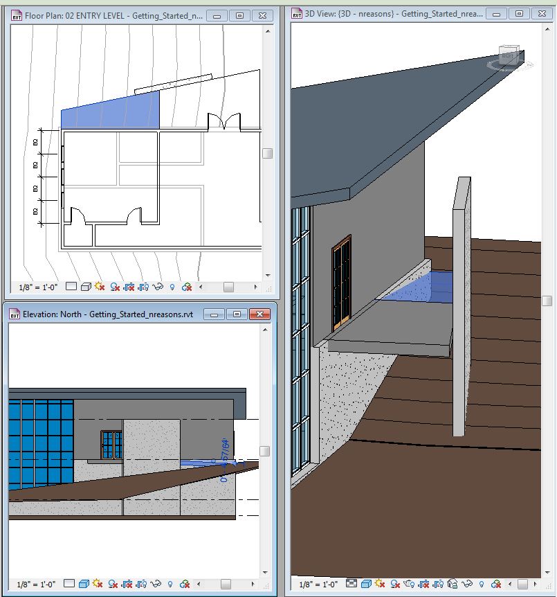
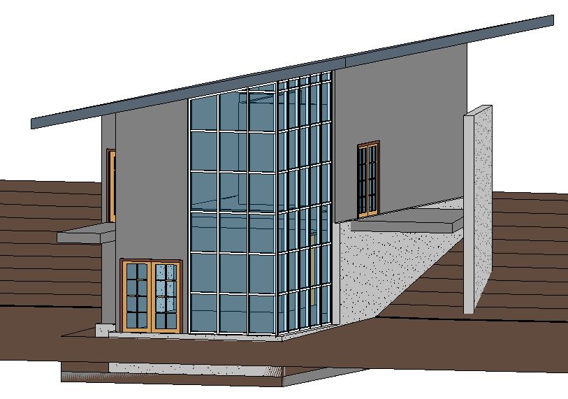
Check work:
Go to a 3d view to view the outcome and check your work. Go back and make revisions as required selecting the Roof element and clicking "Edit Footprint".