I found this great blog with an overview of the BIM implementation process with links to detailed information for each phase. At first pass this looks like a very thorough blog from an experienced BIM professional. These are not software how to's but more what and when to articles.
Initial BIM implementation advice:
http://bradleybim.com/2013/07/24/revit-implementation-puzzle-5-basic-planned-investments/#!
Family creation processes:
http://bradleybim.com/2012/10/30/real-costs-for-building-revit-families-1000-bradley-revit-family-library-models/
Staff training advice:
http://bradleybim.com/2013/02/24/keys-to-designing-your-successful-revit-101-basic-training/
Thursday, January 9, 2014

Monday, October 28, 2013
Family Creation Part 1 (from therevitkid.com)
Great basic intro to family creation! Thanks to the Revit Kid.
These are my personal notes, watch the video.
2. start with reference planes (especially with parametric families) which control geometry. In plan, side and front elevation views.
(keyboard shortcut RP to start drawing ref plane.)
3. add dimensions to the ref. planes. Typically, Width, Length, Height (Labels).
4. add parameters to the dimensions.
5. Start drawing geometry, Extrusion in plan view.
6. Draw extrusion snapping to reference planes. Lock edges to reference planes, Revit lets you do this either in the boundary edit mode or outside of it.
Note: It is recommended to NOT lock edges while in the boundary edit mode as the locks are easier to find when you come back to the Family later and appear when you click on the 3D element. Not having to enter the boundary edit mode to find them will avoid an extra step in the workflow.
Note: It is recommended to NOT lock edges while in the boundary edit mode as the locks are easier to find when you come back to the Family later and appear when you click on the 3D element. Not having to enter the boundary edit mode to find them will avoid an extra step in the workflow.
7. Check work, tile plan, front and 3d views; click and move a ref. plane should change size of 3d box. Changing parameters in Family Types should also affect the size.

This is a recap for me but full of helpful reminders if you haven't created families in a while!
Tuesday, June 12, 2012
Basic Parametric Component (Family)
A Revit 2011 tutorial from youtube, courtesy of https://www.youtube.com/user/ddufon
Video link: http://youtu.be/on4LeYIuCis
Text walkthrough of video:
open generic model family template
Set family category and parameters, can be anything you need. (Light fixtures is used in the video)
In Floor Plan View:
Draw reference planes for parametric ability, define/name them as their correct edges. Left is left, Right is right, Bottom (of screen) is front, Top of screen is back.
Go to Front view:
Draw two reference planes, one over the Ref. Level line (set it as bottom) and one 2' above, set as top.
In Floor Plan and Front View:
Add Aligned dimension between left and right, front and back and top and bottom reference planes, (4'-0" wide).
Cancel out of dimension command.
Modify / Select dimension, On the Options bar, select from the Label: drop down box.
Name them Depth, Width and Height accordingly.
Note: be sure the dimension for Height is to the bottom Reference Plane not Ref. Level.
In Floor Plan and Front View:
Draw a 3d box with the extrusion tool.
Align and lock all edges to reference planes.
Open 3d view:
Add material and visibility parameter in the Family type dialog, click add.
After creating parameters, you must associate them with the object.
Select object, then set parameter association in properties box by clicking the small box to the very right of the parameter that you mean to set/modify.
Video link: http://youtu.be/on4LeYIuCis
Text walkthrough of video:
open generic model family template
Set family category and parameters, can be anything you need. (Light fixtures is used in the video)
In Floor Plan View:
Draw reference planes for parametric ability, define/name them as their correct edges. Left is left, Right is right, Bottom (of screen) is front, Top of screen is back.
Go to Front view:
Draw two reference planes, one over the Ref. Level line (set it as bottom) and one 2' above, set as top.
In Floor Plan and Front View:
Add Aligned dimension between left and right, front and back and top and bottom reference planes, (4'-0" wide).
Cancel out of dimension command.
Modify / Select dimension, On the Options bar, select
Name them Depth, Width and Height accordingly.
Note: be sure the dimension for Height is to the bottom Reference Plane not Ref. Level.
In Floor Plan and Front View:
Draw a 3d box with the extrusion tool.
Align and lock all edges to reference planes.
Open 3d view:
Add material and visibility parameter in the Family type dialog, click add.
After creating parameters, you must associate them with the object.
Select object, then set parameter association in properties box by clicking the small box to the very right of the parameter that you mean to set/modify.
Tuesday, April 24, 2012
Revit Getting Started Guide: Creating a Solar Study
"create an animation of the solar activity at a particular place and time in order to study
the light and shadows that affect the building site."
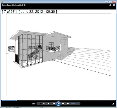


1 Open a 3D view.
2 Adjust Shadow intensity, under View tab and Graphics panel, click the small arrow to the right of the word "Graphics" to open the "Graphic Display Options" dialog box. (keyboard shortcut = GD)
■ Under Shadow, verify that Cast Shadows is selected, and for Contrast, specify 24.
3 Modify the Sun Settings, Click the Sun Icon then, Sun Settings... to open the dialog box.
(the icon is in the Visibility settings menu at the bottom of the view screen)
4 select a city near your location, and click OK.
■ For Date, enter 6/22/2012.
■ For Time Interval, select 15 minutes.
■ Clear Ground Plane at Level so that the shadows fall on the terrain.
■ Click Apply, and then click OK.
5 Preview the solar study, click the sun icon to access this option.
6 Export the animation:
Click File menu ➤ Export➤Images and Animation➤Solar Study
Click ok to save the .avi file to the desired location.
the light and shadows that affect the building site."


1 Open a 3D view.
2 Adjust Shadow intensity, under View tab and Graphics panel, click the small arrow to the right of the word "Graphics" to open the "Graphic Display Options" dialog box. (keyboard shortcut = GD)
■ Under Shadow, verify that Cast Shadows is selected, and for Contrast, specify 24.
3 Modify the Sun Settings, Click the Sun Icon then, Sun Settings... to open the dialog box.
(the icon is in the Visibility settings menu at the bottom of the view screen)
4 select a city near your location, and click OK.
■ For Date, enter 6/22/2012.
■ For Time Interval, select 15 minutes.
■ Clear Ground Plane at Level so that the shadows fall on the terrain.
■ Click Apply, and then click OK.
5 Preview the solar study, click the sun icon to access this option.
6 Export the animation:
Click File menu ➤ Export➤Images and Animation➤Solar Study
Click ok to save the .avi file to the desired location.
Revit Rendering
I am experimenting with rendering, I will post links to helpful hints and some of my own findings as they come.
First few passes:

JPEG, High quality setting
First note, saving to TIFF loses the "sky" and JPEG retains it, no idea why yet. Will update when I find out.
Rendering resources from around the web:http://revitclinic.typepad.com/my_weblog/2009/07/10-rendering-tips.html
http://revitclinic.typepad.com/my_weblog/2010/02/3-more-revit-rendering-tips.html
10 Revit 2011 Visualization Tipshttp://revitclinic.typepad.com/my_weblog/2010/05/10-revit-2011-visualization-tips.html
First few passes:
 TIFF, Default Image exposure settings.
 TIFF, Adjusted exposure...
JPEG, High quality setting
First note, saving to TIFF loses the "sky" and JPEG retains it, no idea why yet. Will update when I find out.
Rendering resources from around the web:http://revitclinic.typepad.com/my_weblog/2009/07/10-rendering-tips.html
http://revitclinic.typepad.com/my_weblog/2010/02/3-more-revit-rendering-tips.html
10 Revit 2011 Visualization Tipshttp://revitclinic.typepad.com/my_weblog/2010/05/10-revit-2011-visualization-tips.html
Revit Getting Started Guide: Documenting the Project
Create a section view from plan, cut through the stair. Command is under View tab.
Room placing - Walls, floors, ceilings and roofs are set by default to be room bounding, this can be controlled in the properties dialog by selecting the element after creating and un-checking the option. Rooms don't create themselves automatically, you must place rooms. Use the Room command found on the Home tab.
Room boundary - Room extents for open spaces can be controlled by the room boundary, adding a line connecting to bounding walls to limit the boundary.
Room tags - Why can't I place a room tag? Well, because you have to "place" the room first, then you can tag it! Command found under the Home tab at Room & Area.
Door and window
tags - Use Tag all command under Annotate tab in floor plan views. Click to modify tag numbers.
Schedules - Create a schedule or the preceding under the View tab, select Schedules / Quantities. Schedules are live and changes done to the plan or the schedule both affect each other. ie. change a window or door family type in the schedule and it will change in plan. (if you do, be sure to check for placement)
Crop boundaries - turn off and on in properties dialog, drag in and out to prepare for placement into a drawing sheet. Crop view and Annotation crop separately, Can NOT draw linework outside of the crop view, must be a symbol / family considered annotation by Revit.
Room color fill - In a plan view, Command under Home tab, Room & Area panel, click Legend. Click to locate on screen in approximate location, you can move it later. Choose Space Type dialog will pop up, select desired options, click ok. Legend appears and rooms become color coded. Highlight the legend and click Edit Scheme under the Modify tab to control room visibility and change color scheme.
All Caps in Revit? Why yes!
I found this blog by the respected Paul F Aubin on how to get Revit to only use All Caps when creating text for schedules and the like. http://paulaubin.com/blog/all-capital-letters-alt-part-2/
Some Caps only fonts to experiment with: http://www.lostinthebox.com/viewtopic.php?t=1495
How to change the default font in Revit: (Comment on this post if you know, or I will add this link/ instruction once I find it, a quick Revit help search doesn't give me a straight answer straight away)
Some Caps only fonts to experiment with: http://www.lostinthebox.com/viewtopic.php?t=1495
How to change the default font in Revit: (Comment on this post if you know, or I will add this link/ instruction once I find it, a quick Revit help search doesn't give me a straight answer straight away)
Tuesday, April 17, 2012
Revit Getting Started Guide: Current Progress
Page 34: Just Finished adding Railings and Modifying the Roof.


Revit Getting Started Guide: Adding a Sloped Floor
Adding a sloped floor to the entry deck to create a ramp up to the entry door.
The blue highlighted element is the outcome of the directions.
 Select floor command, sketch outline in plan. Add Slope Arrow, set tail at West end of outline, set property at -1'-0". finish sketch.
The blue highlighted element is the outcome of the directions.

Revit Getting Started Guide: Modifying Entry Deck
Recently completed the exercise: Modifying the Entry Deck.
This entails modifying the floor boundary to add an exterior deck and wall.
 |
| Model of Training Progress |
This entails modifying the floor boundary to add an exterior deck and wall.
Drawing and Modifying Roofs by Extrusion
How to draw and modify roofs by Extrusion.
Use: Ability to extrude roofs from vertically planar surfaces.
 Command location:
Home tab > Build > Roof dropdown, options: by footprint, by extrusion, by face.
Where:
Must be in a plan view, preferably a Roof plan view that you previously created.
Start command:
Select by Extrusion, use the pick a plane option. Select a vertical face desired, for example a roof fascia. Select desired Level association in the following prompt.
Sketch the line in the shape you want the roof to be. Set extrusion depth in the properties. Finish Sketch.
Connect the new roof extrusion to the existing roof with the Roof Join/Unjoin command.
Use: Ability to extrude roofs from vertically planar surfaces.
 Command location:
Home tab > Build > Roof dropdown, options: by footprint, by extrusion, by face.
Where:
Must be in a plan view, preferably a Roof plan view that you previously created.
Start command:
Select by Extrusion, use the pick a plane option. Select a vertical face desired, for example a roof fascia. Select desired Level association in the following prompt.
Sketch the line in the shape you want the roof to be. Set extrusion depth in the properties. Finish Sketch.
Connect the new roof extrusion to the existing roof with the Roof Join/Unjoin command.
Drawing and Modifying Roofs by Footprint
How to draw and modify roofs by Footprint.
Command location:
Home tab > Build > Roof dropdown, options: by footprint, by extrusion, by face.
Where:
Must be in a plan view, preferably a Roof plan view that you previously created.
Start command:
Select by footprint, check properties dialog and select correct base level and other options. Look at options bar below Ribbon, change accordingly. Here you will set the desired uniform overhang, leave defines slope selected.
Select Walls:
Hover over a wall and press Tab button until a chain of walls is highlighted, select.
You will still be in the "Create Roof Footprint" command/tab.
Clicking the double arrow icon changes the boundary from inside to outside of wall edges, pick inside for a flat roof with parapet walls or outside for a sloped/hipped roof with eaves.
Define slopes:
A triangular roof slope symbol appears next to each boundary line that is set to define the roof slope. (Example: if all boundary lines define a slope then you will have a hip roof) To change this select one or more boundary lines with the Modify tool, once selected look in the options bar below the ribbon to change this setting. Set the options based on the roof slope and configuration desired.
Create complex slopes: Use the Slope Arrow tool available during the boundary edit command. Any start and stop point on a boundary line. Slope Arrows can be used independently by deselecting "defines slope" option for all boundary lines or in conjunction with some boundaries defining slope. Experimentation is required in order to take full advantage of this command.
Set slopes:
Click each boundary line then corresponding roof slope icon to set the actual roof slopes 1/12, etc.
Finish command:
Click green check mark to finish and accept settings.
Check work:
Go to a 3d view to view the outcome and check your work. Go back and make revisions as required selecting the Roof element and clicking "Edit Footprint".
Command location:
Home tab > Build > Roof dropdown, options: by footprint, by extrusion, by face.
Where:
Must be in a plan view, preferably a Roof plan view that you previously created.
Start command:
Select by footprint, check properties dialog and select correct base level and other options. Look at options bar below Ribbon, change accordingly. Here you will set the desired uniform overhang, leave defines slope selected.
Select Walls:
Hover over a wall and press Tab button until a chain of walls is highlighted, select.
You will still be in the "Create Roof Footprint" command/tab.
Clicking the double arrow icon changes the boundary from inside to outside of wall edges, pick inside for a flat roof with parapet walls or outside for a sloped/hipped roof with eaves.
Define slopes:
A triangular roof slope symbol appears next to each boundary line that is set to define the roof slope. (Example: if all boundary lines define a slope then you will have a hip roof) To change this select one or more boundary lines with the Modify tool, once selected look in the options bar below the ribbon to change this setting. Set the options based on the roof slope and configuration desired.
Create complex slopes: Use the Slope Arrow tool available during the boundary edit command. Any start and stop point on a boundary line. Slope Arrows can be used independently by deselecting "defines slope" option for all boundary lines or in conjunction with some boundaries defining slope. Experimentation is required in order to take full advantage of this command.
Set slopes:
Click each boundary line then corresponding roof slope icon to set the actual roof slopes 1/12, etc.
Finish command:
Click green check mark to finish and accept settings.
Check work:
Go to a 3d view to view the outcome and check your work. Go back and make revisions as required selecting the Roof element and clicking "Edit Footprint".
Thursday, March 22, 2012
Getting Started: Creating Levels
Levels are modified and created in building elevation views. Double click an elevation view to work in.
Modify existing: Double click Level name and dimensions to change either.
Create new: Click Level command found under Home tab; Datum.
Offset or draw new, to draw freehand set offset to 0'-0".
Offsetting is recommended as you can control the new level dimension and the extents match the level you are offsetting from.
In the drawing area, highlight an existing Level line; when a dashed line is displayed above or below the level line, click to create a level.
To create a level marker without creating a plan view, good for datum points for the building elevation where a plan may not be needed. Uncheck "Make Plan View" before proceeding with placement.
REVIT 2012 UPDATE:
The offset command no longer works to create new levels. You can still copy but that does not produce additional plans, only an elevation marker in the elevation and section views. To create a new level with associated live plan views you must use the Level command and draw from "scratch".
Modify existing: Double click Level name and dimensions to change either.
Create new: Click Level command found under Home tab; Datum.
Offset or draw new, to draw freehand set offset to 0'-0".
Offsetting is recommended as you can control the new level dimension and the extents match the level you are offsetting from.
In the drawing area, highlight an existing Level line; when a dashed line is displayed above or below the level line, click to create a level.
To create a level marker without creating a plan view, good for datum points for the building elevation where a plan may not be needed. Uncheck "Make Plan View" before proceeding with placement.
REVIT 2012 UPDATE:
The offset command no longer works to create new levels. You can still copy but that does not produce additional plans, only an elevation marker in the elevation and section views. To create a new level with associated live plan views you must use the Level command and draw from "scratch".
Refresher: Getting Started with Revit Architecture
After working for a few months strictly in AutoCAD and not training in Revit for a while, I have opted to do a review practice with the Autodesk Revit tutorial "Getting Started with Revit Architecture" which was developed for 2009 but should still apply for all the basic functions that it covers. I will post reminders as needed from this training, I will see how it goes!
Wednesday, September 22, 2010
Moving On
I will be moving to training on Revit 2011 mostly due to a poll I conducted on the Autodesk User Group International site, AUGI for short. Take a look at the results and user comments here. It proved to be very informative. http://alturl.com/23pb
The Autodesk Assistance program (for students and the unemployed) is still open and has Revit and Autocad 2011 available for download with user licenses as well.
http://bit.ly/aI7rmr
The Autodesk Assistance program (for students and the unemployed) is still open and has Revit and Autocad 2011 available for download with user licenses as well.
http://bit.ly/aI7rmr
Sunday, May 16, 2010
Mastering Revit Architecture 2010 - Ch. 3 Know Your Editing Tools - Editing Elements Interactively: Offsetting Lines and Walls
Mastering Revit Architecture 2010 - Ch. 3 Know Your Editing Tools - Editing Elements Interactively: Offsetting Lines and Walls
"Offset - ...makes a copy of an element by offsetting it parallel to an edge you select. You can find the Offset tool either in the Edit panel of the Modify tab or on the Options bar when you’re sketching lines or walls. ...useful in the Family Editor when you’re making shapes that have a consistent thickness in profile, such as extruded steel shapes. ...handy when you’re making roof forms or soffits with known offsets from a wall. You can either offset a line and maintain the original (for that, make sure that the Copy option in the Options bar is checked) or offset the line, removing the original."
(Options Bar: Numerical - Enter distance to be offset, Hover over the element / wall meant to be offset, dashed line appears on side that it will offset to, one click then done. Graphical - Click element to be offset, then move direction and distance desired, second click to place.)
5.16.10 8:55pm-9:30pm = 35mns
Thursday, May 13, 2010
Mastering Revit Architecture 2010 - Ch. 3 Know Your Editing Tools - Editing Elements Interactively: Scaling and Aligning Elements
Mastering Revit Architecture 2010 - Ch. 3 Know Your Editing Tools - Editing Elements Interactively: Scaling and Aligning Elements
"Scale - lets you scale certain lines and graphic elements in 2D that make sense to scale, such as imported raster images and 2D line shapes."
"note: Keep in mind that you’re working with a building information model (BIM) made out of real-world objects, not abstract primitive forms. Don’t expect to be able to scale most elements in Revit—it’s not practical or meaningful."
"Aligning Elements - ...take time to get acquainted with this tool, because it’s a real timesaver and supplants the need to use many of the tools we’ve already discussed. The Align tool lets you line things up in an easy, quick, and intuitive manner."
"explicitly align references from one element to another."
"find the Align tool in the Modify tab, under the Edit panel. To use the Align tool, you will first select the target reference (a part or side of the element to which you want to align another element) and then select what you want to align to that reference (the part or side of the element whose position needs to be modified)."
"second element picked always moves into alignment."
"As soon as you make your second pick, a lock icon appears so you can constrain the alignment. Once you click the lock icon, if either element moves, it brings the constrained element along with it."
"also works for aligning geometry with surface patterns like brick or stone. Select a line in the surface pattern, and then select the geometry you want aligned. ...Use the Tab key if you cannot get surface patterns selected with the first mouse click."
"...also rotate elements in the process of aligning them to objects which are not parallel."
5.13.10 9:35pm-10:15pm = 40mns
Mastering Revit Architecture 2010 - Ch. 3 Know Your Editing Tools - Editing Elements Interactively: Extending and Splitting Lines and Walls
Mastering Revit Architecture 2010 - Ch. 3 Know Your Editing Tools - Editing Elements Interactively: Extending and Splitting Lines and Walls
"Next to the Trim tool, you will find the Extend tool. There you will see two options: Trim/Extend Single Element and Trim/Extend Multiple Elements."
"This tool lets you extend single or multiple instances of lines and walls. The first option, Trim/Extend Single Element, is for extending a single wall. To extend a wall, first select a target wall; then select the wall you want to extend to that target. The second option, Trim/Extend Multiple Elements, lets you extend many walls in one interaction."
Splitting Lines and Walls - ...operates on walls and lines. This tool lets you slice a line or wall into few pieces. To cut a wall, place the cursor over the edge of the wall. Before you click, you’ll see a preview of the split line before clicking. The Options bar offers ...feature called Delete Inner Segment that removes the need to use the Trim tool."
(I tried this a few times and could not get a clean edge no matter what I did, I suggest Splitting in the middle of the wall you want gone, the using the trim command to get smooth corners)
5.13.10 9:05pm-9:35pm = 30mns
Mastering Revit Architecture 2010 - Ch. 3 Know Your Editing Tools - Editing Elements Interactively: Mirroring and Arraying Elements
Mastering Revit Architecture 2010 - Ch. 3 Know Your Editing Tools - Editing Elements Interactively: Mirroring and Arraying Elements
"Mirror tool - ...allows you to mirror elements across an axis in order to create a mirror image of
an element ...either pick an existing reference in the model (the arrow icon) or draw the axis interactively (the pencil icon). ...Use the pick method when you have an existing element with a meaningful center axis. If nothing in the model exists as a mirror axis, use the Draw mode and draw your own axis."
"Arraying Elements - ...allows you to copy instances of an element with equal spacing between instances. Revit provides intelligent arrays that can be parametrically grouped and associated, as well as one-off, unassociated arrays. Like all the other tools we’ve reviewed, the creation options are presented on the Options bar."
"...two types of array: linear and radial.
Linear arrays - set as the default because they’re the most common. ...creates a series of elements in a line. Each element in the line can be given a set distance from the previous element or be spaced equally based on a maximum line length."
"radial array - works in a similar fashion, but it revolves around a center point. ...elements auto-rotate so that each element faces the center of the array..."
5.13.10 8:44pm-8:57pm = 13mns
Mastering Revit Architecture 2010 - Ch. 3 Know Your Editing Tools - Editing Elements Interactively: Rotating Elements
Mastering Revit Architecture 2010 - Ch. 3 Know Your Editing Tools - Editing Elements Interactively: Rotating Elements
"Rotating and Mirroring Elements - ...Revit provides a few methods for rotating elements. The time-saving spacebar is a quick way to rotate elements in 90-degree increments. Just press the spacebar when an element is selected... If a diagonal reference (wall, grid, or reference plane) is nearby, then the spacebar will locate this as a rotation candidate. For more precision, the Rotate tool is provided..."
"Using the Spacebar - ...to rotate elements both at the time of placement and after an element has been placed. ...a few examples:
Doors and windows - If you have a door with its swing in the wrong direction, select it and press the spacebar. You can cycle through all four possible orientations of the door with a few clicks. The same holds true for windows; however, many window families are built to only let you flip the window from inside to outside, because many windows are symmetrical in elevation. If you are creating an asymmetrical window on your own, be sure to add flip controls to the window family during its creation. These allow the spacebar to work on hosted elements."
"Walls - If you select a wall, pressing the spacebar flips the element as if it were being mirrored
about its length. Walls flip based on the Wall Location Line, which often isn’t the wall centerline.
If you aren’t sure which direction your wall is facing, select it and look for the flip-control
arrows. These are always drawn on the exterior side of walls..."
"Freestanding elements - If you select a freestanding element ...the spacebar rotates the element about the center reference planes defined in the family. Depending on how the family was built, the rotation origin may not make the most sense, but you can quickly orient your furniture and casework. If you decide to edit a family to change the location of the geometry relative to the center reference planes, be careful: when loaded back into a project, all your elements will jump to a new X–Y location based on the changes you made!" (Think editing the base point of a block in AutoCAD, everything will move based on the new basepoint when it's reloaded)
"Rotate tool - To rotate an element, select it and click the Rotate tool. ...two-click operation similar to the Move and Copy tools. Alternatively, you can enter numeric values. Revit locates the geometric center of the selected element or elements and uses that as the default center of rotation. ...fine if you don’t need to be precise... in most cases you first must designate a meaningful center of rotation. ...select and drag the center of the rotation—the rotation cursor—to a new location before clicking to set start and end picks. Once the origin is established, begin rotating the
element using the temporary dimensions as a reference or by typing in the angle of rotation explicitly." (entering positive numbers rotates clockwise, negative rotates counter clockwise)
Note: "...while moving the origin, you lose the ability to pan and zoom the view. To overcome this, drag the origin into the Project Browser and release the mouse button; then, move the cursor back into the view. The cursor changes to a rotation icon, and you can freely pan and zoom all you want. The next click you make places the origin..."
5.13.10 8:15pm-8:42pm = 27mns
Subscribe to:
Posts (Atom)